Comparison of Coatings Adhesion Performances for Buried SS316L Pipelines
1Department of Metallurgical and Materials Engineering, Jadavpur University, Kolkata-700032, India.
2NACE Corrosion Specialist, A/172 Lake Gardens, Kolkata-700045, India.
Corresponding Author E-mail: ghosal.surajit@gmail.com
DOI : http://dx.doi.org/10.13005/ojc/390203
Article Received on : 15 Mar 2023
Article Accepted on : 16 Apr 2023
Article Published : 21 Apr 2023
Reviewed by: Dr. Mallika J
Second Review by: Dr. Syed Abuthahir
Final Approval by: Dr. Tawkir Sheikh
Six polymeric coatings viz. 3LPE, 3p/2p CAT, PU, VE, LE and HSS have been selected and each type of coating has been applied separately on SS316L pipe external surface. The test samples have been subjected to adhesion tests by the peel strength and pull-off methods, before and after the Hot Water Immersion (HWI) test for 100 days. After completing the test, the peel strength values of 3LPE, 3p/2p CAT, VE, HSS are found about 10.9, 1.8, 0.35, 6.8 N/mm respectively, whereas the pull-off adhesion values of PU, LE are found about 10.77, 22.7 N/mm2 respectively. The experimental results are analysed, and the adhesion performances of the coatings are compared based on the dimensionless number termed as the “Coating Bond Index” in this study. The relative rankings of the adhesion performances for these coatings are evaluated in determining coatings suitability for buried SS316L pipelines in the petroleum, petrochemical and natural gas industries.
KEYWORDS:Adhesion performances; HWI test; Polymeric coatings; Peel strength and Pull-off methods; SS316L pipes
Download this article as:| Copy the following to cite this article: Ghosal S, Dey S, Duari B. Comparison of Coatings Adhesion Performances for Buried SS316L Pipelines. Orient J Chem 2023;39(2). |
| Copy the following to cite this URL: Ghosal S, Dey S, Duari B. Comparison of Coatings Adhesion Performances for Buried SS316L Pipelines. Orient J Chem 2023;39(2). Available from: https://bit.ly/43ODLCm |
Introduction
The petrochemical products are transported via buried SS316L pipelines. These pipelines are installed mostly buried and marginally overground. Overground SS316L pipelines do not need corrosion protection due to 1-3 nm (nanometre) thick chromium oxide (Cr2O3) passive layer 1, 2. In buried condition, uncoated SS316L pipeline is excellent in high resistivity soil with a good drainage system 3, but uncoated SS316L pipeline is uncertain in low resistivity soil with chlorides ions (Cl–) and a deficient in oxygen 4. Cl– ions destroy passive layer and lead to form corrosion pits on SS316L surface 5. Pits are covered by the porous corrosion products and remain undetectable until leaks 6. Localized pitting corrosion penetrates rapidly to the thickness of SS316L pipeline and perforates pipeline within a few days 7. The mechanism of pitting corrosion on buried uncoated SS316L pipeline is shown in Figure 1 a), b). It is, therefore, imperative to apply external polymeric (organic) protective coatings on buried SS316L pipelines for safe transportation of the petrochemical products.
A thorough literature survey including analysis of research papers reveals that so far, most of the studies done on polymeric coatings focused primarily on the analysis of coatings performances and suitability for buried carbon steel pipelines. Many researchers have been devoted research efforts to the study of metallic coatings and organic coatings on SS316L substrates for marine environments or to the study of coatings to prevent pitting corrosion of SS316L under thermal insulation. But, to date, less attention has been paid to the research on coatings performances and suitability for buried SS316L pipelines and there is a research gap, which remains unanswered in this field. To address this outstanding gap, in the present study, six external polymeric coatings commonly used for buried carbon steel pipelines have been chosen for buried SS316L pipelines and are applied separately on SS316L pipes. The test samples have been subjected to the adhesion tests, before and after the HWI test.
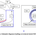 |
Figure 1: (a-b). Schematic diagram of pitting corrosion in buried SS316L pipeline |
Materials and Methods
Chemical composition analysis and corrosion tests of SS316L
The test samples are drawn from 4-inch SS316L pipes for chemical composition analysis and corrosion tests. Cyclic potentiodynamic polarization test 8 has been conducted at 25⁰C using three-electrode system within a glass cell filled up with 3.5% sodium chloride (NaCl) solution according to ASTM Standard Test Method G61 9. Critical Pitting Temperature (CPT) test has been conducted at 22-24⁰C in reagent grade 6% ferric chloride (FeCl3) solution as per ASTM Standard Test Method G48 10 to determine minimum temperature to cause initiation of pitting corrosion.
Surface preparation of SS316L pipes
The external surfaces of 4-inch SS 316L pipes are prepared by fused alumina fine particles for a high level of adhesion 11. Surfaces are made dry and free from contamination prior to coating. Fused alumina particles, original pipe surface and pipe surface after blasting are shown in Figure 2 a), b), and c) respectively.
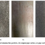 |
Figure 2: (a) Fused alumina fine particles, (b) original pipe surface, (c) pipe surface after blasting |
Types of polymeric coatings
Six types of generic polymeric coatings have been selected and each type of coating has been applied separately on each 4-inch SS316L pipe external surface after surface preparation. The types of coatings are as follows:
3Layer Polyethylene (3LPE)
3ply/2ply Cold Applied Tape (3p/2p CAT)
Solvent free liquid applied Polyurethane (PU)
Non-crystalline Visco-Elastic polyolefin with polymeric tape outer wrap (VE)
Solvent free Liquid applied Epoxy (LE)
Polyethylene based Heat-Shrinkable Sleeve (HSS).
A brief description of each coating system is given below:
3Layer Polyethylene (3LPE)
This anti-corrosion system consists of a three-layer coating system. First layer is a high-performance fusion bonded epoxy primer (FBE, minimum 200 microns) followed by a copolymer adhesive second layer (a maleic anhydride grafted polyethylene compound, about 200-250 microns) and third layer is an outer layer of high-density polyethylene, HDPE (about 2400-2600 microns) with UV stabilizers, which provides tough, durable protection. This coating system is applied in the coating plant only. This coating system provides corrosion protection of buried pipelines at operating temperatures from – 40°C to 80°C.
3ply/2ply Cold Applied Tape (3p/2p CAT)
This is a cold applied multilayer coating system consisting of a liquid adhesive primer (butyl rubber, about 80-100 microns), 3ply anti-corrosion inner layer (a combination of HDPE and LLDPE co-extruded coating, tape thickness about 800 microns) and a mechanical outer layer (MDPE with UV stabilizers, tape thickness about 500 microns). Applied thickness of 3p/2p CAT is about 2500 microns or more. This coating system is applied in the coating plant and in the field. This coating system provides corrosion protection of buried pipelines at maximum operating temperature of 60°C.
Liquid applied Polyurethane (PU)
This is a thermoset aromatic polyurethane, which is a reaction product between a polyol (resin) and a diphenylmethane diisocyanate (MDI, activator). Liquid applied PU coating is solvent free (100% volume solid). Applied thickness of PU is about 1000-1500 microns in a single coat. This coating system is applied in the coating plant and in the field. This coating system provides corrosion protection of buried pipelines at operating temperaturesfrom – 20°C to 80°C.
Non-crystalline Visco-Elastic Polyolefin with polymeric tape outer wrap (VE)
This is a cold applied non-crystalline, non-cross-linked, non-reactive poly-isobutene wrap (about 2000-2500 microns thick) with a direct bond to the substrate. Over poly-isobutene wrap, an ultraviolet resistant flexible polyvinyl chloride (PVC, about 500 microns thick) tape coated with a rubber resin adhesive is applied. This coating system is applied in the coating plant and in the field. This system provides corrosion protection for buried pipelines at maximum operating temperature of 60°C.
Liquid applied Epoxy (LE)
This is a high-build solvent free (100% volume solid) two-component (part-A and part-B) novalac based epoxy. Applied thickness of LE is about 800-1500 microns in a single coat. This coating system is applied in the coating plant and in the field. This coating system provides corrosion protection of buried pipelines at maximum operating temperature from – 20°C to 80°C.
Heat-Shrinkable Sleeve (HSS)
This is a wrap-around heat-shrinkable sleeve, which replicates the plant applied 3LPE coating. First layer is solvent free two component liquid epoxy primer (about 200 microns), second layer is co-polymer hot melt adhesive (about 200 microns), and third layer is radiation cross-linked HDPE with UV stabilizers (about 2000-2500 microns thick). This coating system is mostly applied in the field for pipe-to-pipe field-joints and is sometimes applied in the coating plant for pipe bend joints. This coating system provides corrosion protection of buried pipelines at maximum operating temperature of 80°C.
Preparation of test samples – thickness measurements and holiday tests
The test samples are prepared after cold cutting pipe segments from main 4-inch coated pipes for adhesion tests. The thickness measurement of each coating has been performed by digital thickness gauge. The entire surface of each coating has been subjected to holiday test applying a range of voltages based on the type of coating and thickness as per NACE Standard SP0274 12 to ensure each coating surface free from holidays (pinholes or defects).
HWI test of coatings
The purpose of HWI test is to subject coated test samples to the effects of long-term water exposure at a defined temperature and for a specified duration. After completion of the test, the samples are tested on their physical properties like adhesion by the peel strength or pull-off method. HWI test method measures the loss of adhesion strengths of the coatings due to water immersion and the results are compared to the coatings adhesion performances. Two sets of coated test samples are prepared because the adhesion tests are destructive in nature.
For the first set of test samples and prior to the HWI test, the adhesion strengths of 3LPE, 3p/2p CAT, HSS, VE have been measured by the peel strength methods in accordance with ISO 21809-3 13 and the adhesion strengths of LE, PU have been measured by the pull–off methods in accordance with ISO 4624 14.
The second set of test samples have been subjected to the HWI test. The test samples cut edges are sealed with silicone sealant to prevent water ingress from the sides of the samples. After curing the sealants, the test samples are fully immersed under the water in a vessel. The HWI test has been performed placing the vessel in a thermostatically controlled oven to maintain test temperatures about 55±5⁰C for a period of 100 days as per ISO 21809-3. Figure 3 a), b), c) show the thermostatically controlled oven and test samples. After completion of 100 days, these test samples are removed from the heated vessel and allowed them to cool to 23-25⁰C. The adhesion strengths of 3LPE, 3p/2p CAT, HSS, VE and LE, PU have been measured by the peel strength and pull-off methods respectively.
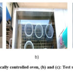 |
Figure 3: (a). A thermostatically controlled oven, (b) and (c): Test samples of coating materials |
Adhesion test by peel strength method
This test method measures the peel strength (peeling force per unit width) between the coating and the rigid metal substrate. The peel strength tests of 3LPE, 3p/2p CAT, HSS, VE coatings on SS316L substrates have been performed with a universal tensile testing machine, Tinius Olsen (Model No. H10KT) 15. A schematic diagram of peel strength method and a universal tensile testing machine are shown in Figure 4 a) and b) respectively.
A sample coating strip is cut in the circumferential direction of test sample, measuring 160 mm long and 25 mm to 50 mm wide. The cut end of the strip is secured to the gripping jaw of the tensile testing machine. The strip is peeled with a peel rate of 10 mm/minute perpendicular to the test sample axis. Each test has been performed at 23-25°C. During testing, the peel-force (vertical y-axis) versus length (horizontal x-axis) graph is generated for each coating of the three samples. From this graph, the peel strength of a sample has been evaluated from the average force and the arithmetic mean over 100 mm length using the Equation [1]. The peel strength of each coating has been computed from the arithmetic mean value of the three samples.
Ppeel = F/w ………… [1]
Where,
F = Average force to peel the coating in Newton, N (or Pound, lb)
w = Width of the coating in millimeter, mm (or inches, in)
Ppeel = Peel strength achieved at failure in N/mm (or lb/in).
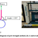 |
Figure 4: (a). Schematic diagram of peel strength method, (b) A universal tensile testing machine |
Adhesion test by pull-off method
This test method covers a procedure for determining the pull-off adhesion strength of a coating on rigid metal substrate. The pull-off adhesion tests of LE, PU coatings on SS316L substrates have been performed with a portable adhesion tester, DeFelsko (Model No. PosiTest AT-A20) 16. A schematic diagram of pull-off method and a portable adhesion tester are shown in Figure 5 a) and b) respectively.
The rigid flat face of each steel dolly of 20 mm diameter is bonded directly to the surface of the test sample using epoxy adhesive at one end. The other end of steel dolly facilitates for connecting the portable adhesion tester. After curing of the adhesive, each dolly is pulled-off by the portable adhesion tester applying tensile stress in a direction perpendicular to the surface of the test sample. Each test has been performed at 23-25°C. The force required to detach each dolly from the coating is measured. The pull-off adhesion strength of a sample has been evaluated from the tensile stress using the Equation [2]. The pull-off adhesion strength of each coating has been computed from the arithmetic mean value of the three samples.
Ppull = 4F/πD2 ……………….. [2]
Where,
F = Force required to detach the dollies in Newton, N (or Pound, lb)
D = Diameter of the original surface area stressed in millimeter, mm (or inches, in)
Ppull = Pull-off adhesion strength achieved at failure in N/mm2 (or Psi)
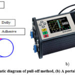 |
Figure 5: (a). Schematic diagram of pull-off method, (b) A portable adhesion tester |
Results and discussion
Chemical composition analysis and corrosion tests of SS316L
The chemical composition analysis and corrosion tests results of SS316L are reported in Table 1. The chemical composition analysis conforms to ASTM Standard Specification A312 17. The cyclic potentiodynamic polarization plots of test samples are shown in Figure 6. From the polarization plots, EPIT values are evaluated. It is observed from the polarization plots that from EPIT, the current increases sharply indicating transition to transpassive corrosion, which is a state of rapid dissolution of metal resulting in significant pitting corrosion and the destruction of protective Cr2O3 passive film on SS316L surface in the presence of Cl– ions. The significant pitting corrosion has been observed under Scanning Electron Microscopy (SEM) examination after cyclic potentiodynamic polarization test and is shown in Figure 7. CPTs have been found to be 15-16⁰C, which indicate that SS316L is susceptible to localized pitting corrosion in chloride bearing environments much below room temperature.
Table 1: Chemical composition analysis and corrosion test results of SS316L
|
%C |
%Mn |
%S |
%P |
%Si |
%Cr |
%Ni |
%Mo |
N (ppm)* |
%Fe |
Epit (mV) vs. SCE ** |
CPT (⁰C) |
|
0.021 |
1.24 |
0.005 |
0.042 |
0.26 |
16.32 |
10.05 |
2.03 |
380 |
Balance |
361 |
16 |
|
0.022 |
1.25 |
0.004 |
0.043 |
0.27 |
16.08 |
10.06 |
2.03 |
395 |
Balance |
363 |
15 |
|
0.018 |
1.27 |
0.004 |
0.043 |
0.20 |
16.29 |
10.05 |
2.04 |
440 |
Balance |
380 |
16 |
(ppm)* – parts per million
SCE ** – Saturated Calomel Electrode as reference electrode
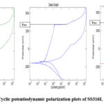 |
Figure 6: Cyclic potentiodynamic polarization plots of SS316L test samples |
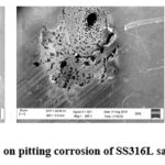 |
Figure 7: SEM photographs on pitting corrosion of SS316L samples after polarization test |
Thickness measurements and holiday tests results of coatings
The average thicknesses of the coatings in mm and a range of applied voltages in kV for holiday tests are shown in Table 2.
Table 2: Thickness Measurement (in mm) and Holiday Test (in kV) of coatings
|
Type of coating |
1 |
2 |
3 |
4 |
5 |
6 |
7 |
8 |
Av.* |
Vol.** |
Holidays |
|
3LPE |
2.96 |
2.93 |
2.89 |
2.93 |
2.98 |
2.86 |
2.85 |
2.80 |
2.9 |
20 – 22 |
Nil |
|
3p/2p CAT |
2.48 |
2.52 |
2.55 |
2.49 |
2.51 |
2.52 |
2.45 |
2.48 |
2.5 |
19 – 20 |
Nil |
|
PU |
1.7 |
1.65 |
1.49 |
1.5 |
1.48 |
1.57 |
1.58 |
1.43 |
1.55 |
8 – 12 |
Nil |
|
VE |
3.03 |
3.09 |
3.07 |
2.95 |
2.91 |
3.03 |
2.89 |
3.1 |
3.0 |
22 – 25 |
Nil |
|
LE |
0.96 |
1.06 |
0.92 |
0.97 |
0.92 |
0.9 |
0.92 |
0.95 |
0.95 |
5 – 10 |
Nil |
|
HSS |
2.31 |
2.22 |
2.45 |
2.3 |
2.46 |
2.24 |
2.2 |
2.22 |
2.3 |
16 – 18 |
Nil |
Av.* – arithmetic mean of thickness
Vol.** – a range of applied voltages
Adhesion test by peel strength method
Figure 8 and Figure 9 show the peel strength graphs of 3LPE, 3p/2p CAT, VE, HSS, before and after the HWI test, respectively. The test samples, before and after the HWI test, are shown in Figure 10 and Figure 11 respectively. Prior to the HWI test, the peel strength of coating is considered as the initial peel strength and is represented as P0. Similarly, after the HWI test, the peel strength of coating is considered as the final peel strength and is represented as P100. The P0 and P100 values are shown in Table 3. It reveals from Table 3 that 3LPE has shown a substantial reduction in the adhesion strength after the HWI test, whereas HSS and VE have shown a slight reduction in their adhesion strengths.
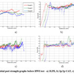 |
Figure 8: Initial peel strength graphs before HWI test – a) 3LPE, b) 3p/2p CAT, c) VE, d) HSS |
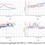 |
Figure 9: Final peel strength graphs after HWI test – a) 3LPE, b) 3p/2p CAT, c) VE, d) HSS |
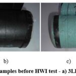 |
Figure 10: Peel strength tested samples before HWI test – a) 3LPE, b) 3p/2p CAT, c) VE, d) HSS |
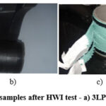 |
Figure 11: Peel strength tested samples after HWI test – a) 3LPE, b) 3p/2p CAT, c) VE, d) HSS |
Table 3: Peel strength results of coatings.
|
Type of coating |
P0 (N/mm) |
P100 (N/mm) |
|
3LPE |
19.7 |
10.9 |
|
3p/2p CAT |
3.4 |
1.8 |
|
VE |
0.39 |
0.35 |
|
HSS |
7.3 |
6.8 |
Adhesion test by pull-off method
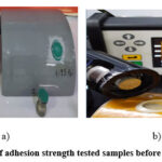
Figure 12 and Figure 13 show the pull-off adhesion strengths of LE and PU in Psi unit, before and after the HWI test, respectively. Prior to the HWI test, the pull-off adhesion strength of coating is considered as the initial pull-off adhesion strength and is represented as P0. Similarly, after the HWI test, the pull-off adhesion strength of coating is considered as the final pull-off adhesion strength and is represented as P100. The P0 and P100 values are shown in Table 4. It is apparent from Table 4 that PU has shown a substantial reduction in the pull-off adhesion strength after the HWI test, whereas LE has shown marginally less reduction in the pull-off adhesion strength.
 r r |
Figure 12: Initial pull-off adhesion strength tested samples before HWI test – a) LE, b) PU |
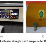 |
Figure 13: Final pull-off adhesion strength tested samples after HWI test – a) LE, b) PU |
Table 4: Pull-off adhesion strength results of coatings.
|
Type of coating |
P0 (N/mm2) |
P100 (N/mm2) |
|
PU |
20.87 |
10.77 |
|
LE |
28.97 |
22.7 |
As the peel strengths of 3LPE, 3p/2p CAT, VE, HSS and the pull-off adhesion strengths of LE, PU are expressed in N/mm and N/mm2 units respectively, it appears unfeasible to draw a comparison of the coatings adhesion performances. In this situation, it has been deduced that it is reasonable to compute the ratio (P100/P0)of each coating to obtain a dimensionless number, which is found to be useful in comparing the coatings adhesion performances after the HWI test and drawing a logical conclusion. This dimensionless number is termed as the “Coating Bond Index” in this study. This index represents as the bond between a coating and SS316L substrate and also the adhesion performance of a coating. The highest index number indicates the strongest bond and best adhesion performance of a coating that ensures the coating remains adhered to SS316L substrate surface for long.
The “Coating Bond Index” has been computed from the ratio (P100/P0)for each coating and is shown in Figure 14. It is apparent from Figure 14 that HSS has the strongest bond between HSS coating and SS316L substrate and has shown best adhesion performance among the coatings after the HWI test. Next to HSS, VE and LE have the stronger bonds and have shown better adhesion performances. PU, 3p/2p CAT and 3LPE have shown almost a relatively same level of the adhesion performances after the HWI test. Therefore, the relative rankings of adhesion performances for these coatings are found to be HSS-1, VE-2, LE-3, 3LPE/3p-2P CAT/PU-4, where ‘1’ represents the strongest bond and best adhesion performance.
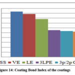 |
Figure 14: Coating Bond Index of the coatings |
Conclusions
The initial high adhesion strength of a coating before the HWI test cannot be ensured to be retained in terms of lifetime of a pipeline because a coating practically loses its original adhesion strength and the main problem encountered with coating failures has been loss of adhesion over time. In such situation, the HWI test has advantage as this is the most realistic method for determining expected long-term adhesion performance of a coating under actual operating conditions. The HWI test measures the loss of adhesion strength of a coating to in-service immersion conditions at a defined temperature and for a specified duration. It is, therefore, logical to conduct adhesion tests on newly coated pipe after the HWI test at temperatures about 55±5⁰C for a period of 100 days and compare the adhesion strength to the original (initial) value. A good coating would then be one that retained a substantial percentage of its original (initial) adhesion strength, or at least some level of adhesion strength after 100 days hot water immersion and is expected to perform a useful life of at least 25-30 years under actual operating conditions.
In this study, the adhesion strength of each coating, before and after the HWI test, has been measured. A comparison of the coatings adhesion performances has been drawn based on the dimensionless number termed as the “Coating Bond Index”. According to the “Coating Bond Index”, HSS has shown the strongest bond and best adhesion performance among the coatings, whereas VE & LE have shown the stronger bond and better adhesion performances for buried SS316L pipelines in the petroleum, petrochemical and natural gas industries. PU, 3p/2p CAT and 3LPE have shown almost a relatively same level of the adhesion performances. The relative rankings of the adhesion performances for these coatings are HSS-1, VE-2, LE-3, 3LPE/3p-2P CAT/PU-4, where ‘1’ represents the strongest bond and best adhesion performance.
Acknowledgement
The authors gratefully acknowledge the cooperation and assistance of Gujarat Industrial Research and Development Agency (GIRDA), Seal for Life and Jindal Stainless Steel Laboratories in providing access to the testing facilities and data.
Conflicts of interest
The authors declare no conflict of interest.
Funding Sources
There was no financial support for the investigation.
References
- ASM Handbook, Vol. No.13,” Corrosion”, fourth printing (1992), ASM International, Ohio, USA, p.3020
- C.-O.A. Olsson, D. Landolt, “Passive films on stainless steels – chemistry, structure and growth”, Electrochimica Acta, April 2003, p.1093
CrossRef - Australian Stainless Steel Development Association (ASSDA), “Guidelines for Use of Stainless Steel in the Ground”
- L. Sjögren, G. Camitz, J. Peultier, S. Jacques, V. Baudu, F. Barrau, B. Chareyre,A. Bergquist, A. Pourbaix, P. Carpentiers, “Corrosion resistance of stainless steel pipes in soil”, European Commission, Technical Steel research, Final report 2008, p.15
- A. JohnSedriks, “Corrosion of Stainless Steels”, Second Edition (1996), Chapter 4, John Wiley & Sons, Inc., Hoboken New Jersey, p.102
- D.A.Jones, “Principles and Prevention of Corrosion”, Chapter 7, Macmillan Publishing Company, New York, p.198
- ASM Handbook, Vol. No.13B, “Corrosion: Materials”, First printing (November 2005), ASM International, Ohio, USA, p.62
- Robert G. Kelly, John R. Scully, David W. Shoesmith, and Rudolph G. Buchheit, “Electrochemical Techniques in Corrosion Science and Engineering”, Chapter 3, Marcel Dekker, Inc. New York, p.104-107
- ASTM G61, “Standard Test Method for Conducting Cyclic Potentiodynamic Polarization Measurements for Localized Corrosion Susceptibility of Iron-, Nickel-, or Cobalt-Based Alloys”
- ASTM G48, “Standard Test Methods for Pitting and Crevice Corrosion Resistance of Stainless Steels and Related Alloys by Use of Ferric Chloride Solution”
- British StainlessSteel Association, “Paint coating stainless steels”
- NACE Standard SP0274, “High-Voltage Electrical Inspection of Pipeline Coatings”, NACE International, Houston, Texas, USA
- International Standard, ISO 21809-3, Petroleum and natural gas industries – External coatings for buried or submerged pipelines used in pipeline transportation systems – Part 3: Field joint coatings
- International Standard, ISO 4624, Second Edition, Paints and varnishes – Pull-off test for adhesion
- Tinius Olsen Ltd. 6, Perrywood Business Park, Honeycrock lane, Salfords (Near Redhill), Surrey RH15DZ, England
- DeFelsko Corporation, 800 Proctor Avenue, Ogdenburg, NY 13669-2205, USA
- ASTM A312, “Standard Specification for Seamless, Welded, and Heavily Cold Worked Austenitic Stainless Steel Pipes”, ASTM International.

This work is licensed under a Creative Commons Attribution 4.0 International License.


