The Potential of High Moisture Biomass for Energy Production Using Plasma – Assisted Gasification
Naiyawat Sukthang1, Pansa Liplap1, Weerachai Arjharn1 and Thipsuphin Hinsui2
1School of Agricultural Engineering, Institute of Engineering, Suranaree University of Technology, 111 University Avenue, Muang District, NakhonRatchasima, 30000, Thailand.
2Center of Excellent in Biomass, Institute of Engineering, Suranaree University of Technology, 111 University Avenue, Muang District, NakhonRatchasima, 30000, Thailand.
Corresponding Author E-mail: naiyawat47@hotmail.com
DOI : http://dx.doi.org/10.13005/ojc/330425
Gasification of biomass has been widely used for energy production. However, biomass feedstock must be low in moisture (< 20 % w.b.), inevitably requiring drying process which is both energy and time consuming. This paper shows the potential of high-moisture biomass gasifying using plasma arc as an external heat supply. It was found that high-moisture biomass can be used as feedstock in the plasma-assisted gasification process. The plasma arc maintained gasifier temperature high enough for reactions involved. The efficiency of the plasma-assisted gasification system operated with high-moisture biomass was more or less the same with that of conventional gasification operated with low-moisture biomass. When the drying energy was taken into account, the efficiency of the plasma gasification system is 15% higher than that of conventional gasification system. Overall, the plasma-assisted gasification system can be operated with high-moisture biomass efficiently and reduces the processes and energy for biomass preparation.
KEYWORDS:Plasma-assisted gasification; fixed-bed downdraft gasifier; energy production; high-moisture biomass
Download this article as:| Copy the following to cite this article: Sukthang N, Liplap P, Arjharn W, Hinsui T. The Potential of High Moisture Biomass for Energy Production Using Plasma – Assisted Gasification. Orient J Chem 2017;33(4). |
| Copy the following to cite this URL: Sukthang N, Liplap P, Arjharn W, Hinsui T. The Potential of High Moisture Biomass for Energy Production Using Plasma – Assisted Gasification. Orient J Chem 2017;33(4). Available from: http://www.orientjchem.org/?p=35704 |
Introduction
Currently,many countries are paying increasing attentiontodevelop renewable energy resources. However, they are still not able to completely replace fossil fuels due to technological, environmental and social problems. In Thailand, Alternative Energy Development Plan (AEDP)has established for promoting renewable energy utilization including different types of renewable energy including solar energy, wind, water, waste, biogas and biomass.1As Thailand is agricultural country, a great deal amount of agricultural residues is left, which could be used as a resource of biomass energy.Furthermore, the use of biomass fuel can also reduce greenhouse gas emissions compared to that of fossil fuels.
Biomass can be converted to energy via either biologicalor thermochemical processes, the latterinclude combustion, pyrolysis and gasification. Gasification is attractivebecause the system is relatively simple, producing a clean-burning fuel witha greater overall conversion efficiency into electric power compared to combustion based technologies.2Technically,it is a technology operated a limited oxygen supply at temperature commonly from 750 up to 1,000°C. The heat transforms solid fuel into syngas, which is combustible, consisting of carbon monoxide (CO), hydrogen (H2)and methane(CH4).3It can be used to produce power in an internal combustion engine to generate electricity, or used as fuel gas in a burner to produce heat.
Gasification process is affected by a number of variables both chemically and physically such as biomass type, size, shape, porosity, bulk density, ash content, etc.4Among these, moisture content is one of the most important factor affecting gasification, especially in downdraft gasifiers.5Arjharn et al.,2reported that the 100-kW fixed bed downdraft gasification was difficult to operate continuouslyif the biomass feedstockscontain moisture content higher than 20%(w.b.). In addition, the higher moisture content of biomass would normally generate high tar content in the syngas because of the drop of gasifier temperature. Thelarger tar content reduces the heating value and clog-up gas pipelines or engines.6Therefore, the use of biomass feedstocksentails several preparation processes, which result in the high cost of production, especially from the drying process. However, uncontrolled biomass quality will reduce the gasification system efficiency as a consequence.
The solution to these problems might be achieved by maintaining the appropriate gasifier temperature during gasification process. Recently, there is a study suggesting that using plasma arc as the supporting heating source for gasification can keep a desired range of temperatures, solving the problem of physical variance in a high-moisture biomass feedstock, since plasma arc can build up temperatures higher than 1,500°C and increase the reaction rate.7 Moreover, the heat from plasma arc can compensate the heat losses in the system8 and reduce an amount of tar in the biomass.9 Nonetheless, an application of plasma arc technology in a heating process in order to improve gasification system is little found in literatures and most of them were carried out in the laboratory scale.9,10 Therefore, theresearches on plasma-assisted gasification at a pilot scale using a high-moisture feedstock would be an alternative approach of energy production. In the present paper, biomass with varying high moisture levels (16-34%w.b.) was served as raw material to test the plasma-assisted gasification system. The study was carried out by assessing gasifier temperature, produced gas quality and system efficiency.
Materials and Methods
Fuel Sample
Giant Leucaena (Leucaenaleucocephala (Lam.) de Wit) stems with 30–40 mm in diameterwere selected and cut into 50–60 mm lengths using a circularsaw(Figure 1).The moisture content levels used were 16%, 28%and 34%w.b. The highest moisture level used is freshly cut wood, while the medium and low ones were obtained after sun drying for a different periods of time.Proximate analysis, such as moisture content, ash, volatile matter and fixed carbon, followed the standard of ASTM D1762-84, and the heating values was determined using a bomb calorimeter as per ASTM D2015-77standard.Ultimate analysis was carried outfor the amount of carbon, hydrogen, nitrogen and sulfur using CHNS-932 EDXRF analyzer. Theoxygen content was calculated by means of the element difference.2
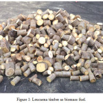 |
Figure 1: Leucaena timber as biomass fuel. |
Experimental Equipment
A direct current (DC) plasma torch obtained from High Temperature Technologies Corp., Chateauguay, QC, Canada, was used to provide additional heat for the study of high-moisture feedstock gasification. The setup included a 50-kW plasma torch, high voltage oscillator, high voltage power supply system, and water supply system. Electricity was transformed into the thermal plasma arc through electrodes made from tungsten (cathode) and copper (anode). The operational voltage and current of the torch were 300 V and 120 A, respectively. Compressed air with a relative pressure of 700 kPa, which is used as the plasma-forming gas, was injected between these 2 electrodes to establish the arc. The intense heat generated on the 2 electrodes was cooled down using cold water from the water supply system that was maintained at 10ºC. The temperature of the water leaving the plasma torch was controlled at < 50°C to avoid the damageof rubber seals. The simplified schematic of the plasma arc torch and its specifications are shown in Figure 2 and Table 1, respectively.
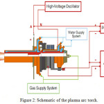 |
Figure 2: Schematic of the plasma arc torch. |
Table 1: Specification of the plasma arc torch (Model :Gas Plasma Arc Torch AK–1–50DC).
| Parameter | Value |
| Power | 50 kW |
| Voltage (max) | 300 V |
| Current (max) | 250 A |
| Air | 2.8 g s–1 |
| Water (max) | 500 g s–1 |
| Life time of electrodes | 200 h |
| Efficiency | 65% |
| Diameter of nozzle | 25 mm |
| Sizes | 30 × 60 mm |
| Weight | 10 kg |
The gasifier is based on a fixed bed downdraft gasifier which was collaboratively designed and developed by the Suranaree University of Technology, Thailand and Satake Corporation Co., Ltd., Japan. The gasifier was manufactured from mild steel and equipped with an inner lining of insulation and high temperature ceramic. The gasifier height and inner diameter were 3.11 m and 0.75 m, respectively. The plasma torch was installed in the combustion zone, approximately 2.28 m from the top of the reactor. A screw conveyor with a water jacket was installed for charcoal removal. Nine air nozzles with a diameter of 10 cm were installed around the combustion zone. The gas cleaning and cooling system was located next to the gasifier, including a cyclone collector, water scrubber, chilled water scrubber, and bag filters. The various elements of the downdraft gasification power plant are shown in Figure 3 and the plasma gasification process is shown in Figure 4.
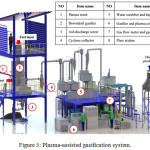 |
Figure 3: Plasma-assisted gasification system. |
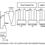 |
Figure 4: Schematic view of a pilot-scale downdraft biomass gasification. |
Experimental Method
Giant Leucaena fuel was delivered to the reactor with an electric hoist. Workers manually filled the fuel until it reached the predetermined level. All valves at the air tube were opened in order to let the air flow into the reactor. Then the scrubber was turned on to run the system, and the fuel was lighted with a plasma torchat the combustion zone. The heat generated in this zone would evaporate from fuel in the drying zone and cause gasification. After gasification was complete, syngas would come out of the reactor and flow to the gas cleaning and cooling system.Contaminants composed mainly of tar and dust in the syngas were eliminated by the cyclone, followed by the water scrubber and chilled water scrubber. As tar is condensed at low temperatures, large amounts of tar will be eliminated at the chilled water scrubber.Finally, bag filters,which can entrap particulate matters as small as0.1 mm, were used for the final stage prior tothe syngas passing to the flare station. The syngas flow rate was held at the best performance of the blowerat 220 (Nm)3 h-1. The flow rate was monitor usingan electronic flow meter (Model DIG-SIDO-O, Nippon Flow Cell Co., Ltd, Tokyo, Japan) which was installed between the bag filters and gas flare. Each test was operated for four hours. The amount of biomass to refill the reactorto the predetermined level, with respect to time,was used to calculate the feedstock consumptionrate. The ash discharge was controlled to be thesame at 5% for all the experiments.
For the temperature distribution inside the reactor, 6 K-type thermocouples were installedvertically at 0.66, 1.06, 1.46, 1.86, 2.28 and 2.70 mdownwards from the top of the gasifier. The protrusion of the thermocouplesfrom the gasifier wall was 10 cm. The temperatureswere measured at intervals of 5 min to recordthe thermochemical conversion phases: drying,pyrolysis, combustion, and reduction.2, 11
The composition of the syngas was analyzed usingan online infrared gas analyzer (Model Gasboard-3100, Wuhan Cubic Optoelectronics Co., Ltd., Wuhan, China) located at between the bag filters andthe flare station. Tar and dust contents were measured by drawing thegas using a vacuum pump. The moisture content in the syngas was measured by CaCl2 contained in a U-shaped tube, which was submergedin ice. Then, approximately
300 L of syngas was drawn through a paper filter (GF/B) with a 47 mm diameter. The total tar anddust contents were quantified by drying thepaper filter in an oven at 105°C for about 6 h.12The dried filter thenwas rinsed with anisole to wash away tar fromthe filter. The difference in weight of the filterafter drying was used to calculate the individualtar and dust contents with respect to the dry gasvolume. The data on the syngas composition andthe tar and dust contents was collected every5 min and 30 min, respectively.
The performance of the gasification system was evaluated by the following equation:13
ηcg=(Vg*LHVg)/(mfuel * LHVfuel)+Ptorch (1)
ηcg=the cold-gas efficiency (%)
mfuel=the waste reject consumption rate (kg h-1)
LHVg=the calorific value of the gas produced (MJ (Nm)-3)
LHVfuel=the low heating value of the rejected waste (MJkg-1)
Vg=the volume flow rate of the gas produced (Nm3 h-1)
Ptorch=the power input for the plasma torch (MJ h-1)
Results and Discussion
Biomass Fuel Characteristics
Table 2 shows characteristics of biomass raw material at different moisture content. The increase in moisture content causes an increase in bulk density but decrease the calorific value. It implies that less energy is generated during the biomass decomposition because partialheat is lost for moisture evaporation during gasification process. In other words, the gasifier temperature will drop when feedstock has high moisture content, resulting in incompletely pyrolysis process during gasification.14Susastriawan et al.,5reported that feedstock with moisture content higher than 30% produces low quality syngas gas, thus low gasification efficiency. Eventually, the downstream applications (turbine, engine and gas burner) cannotoperate efficiently. Normally, to cope with the high-moisture biomass material, the drying process is inevitably needed. However, this process is time consuming and requires a great amount of energy.
For the proximate valuesof Giant Leucaena consisting of volatile matter, fixed carbon and ash contents are 80.94%, 17.53% and 1.53%, respectively.These values are in the range of biomass materials in Thailand as reported by Arjharn et al.,2that studied electricity production from different biomass feedstocks (10 types of feedstock) using a pilot-scale downdraft gasifier. The ultimateanalysis indicated that elemental-basis carbon (C) and hydrogen (H) proportions of the Giant Leucaena (Table 2), principal elements contributing to syngas productionduring thermochemical reactions, were fairly highand suitable for use in gasification process.The proportion of nitrogen and sulfur was found with a small value (< 1%), which is consistent with the study reported by Quaak et al. 15
Table 2: Characteristics of the biomass fuel.
| Analysis | Parameter | Value | ||
| Physical Properties | Moisture Contents (%w.b.) | 16.02 | 28.12 | 34.28 |
| Density (kg/m3) | 335.95 | 391.94 | 427.57 | |
| Size (mm) | L = 50 – 70 mm, Ø = 25 – 60 mm | |||
| Calorific Value (MJ/kg) |
Higher Heating Value | 16.02 | 13.73 | 12.59 |
| Lower Heating Value | 14.54 | 12.12 | 10.92 | |
| Proximate Analysis (wt%, d.b.) |
Volatile Matter | 80.94 | ||
| Fixed Carbon | 17.53 | |||
| Ash | 1.53 | |||
| Ultimate Analysis (wt%, d.b.) |
Carbon | 49.20 | ||
| Hydrogen | 6.05 | |||
| Nitrogen | 0.47 | |||
| Sulphur | 0.03 | |||
| Oxygen | 42.74 | |||
Temperature Profile
Gasifier temperature is a crucial parameter for syngas production. The thermochemical reactions cannot take place efficiently if the temperature is too low. An increase in feedstock moisture content will inevitably cause the drop in gasifier temperature. Biomass with more than 30% moisture content reduces calorific value of syngas.14The effect of different moisture levels (16, 28 and 34% w.b.) on temperature profile when using plasma arc as an additional heat to deal with high-moisture biomass is shown in Figure 5.It was found that the gasification systemwas able tooperate regularly and continuously although the moisture content was over 30% w.b.At the lowest level of moisture content (16% w.b.), the temperature slightlyincreased between the 0.66and 1.06 m positions with an average of 80ºC. The drying process took place in this zone. The moisture in the feedstock is evaporated until the temperature increases up to 200ºC.11Subsequently, the temperature increase rapidly between the 1.06 and 2.28 m positions (~ 900ºC), where the plasma arc and airweresupplied to the gasifier.The pyrolysis takes place at temperature between 200 and 700°C,5 leave releasing volatile consisting mainly of CO and tar and leaving tar behind. At temperature of between 800 and 900°C, the combustion occurred, transferringheat to promote reactions in other zones. At the last stage (between 2.28 and 2.70 m), the temperature dropslightly to ~ 800ºC because ofendothermic reactions by which the productgases produced from the upper zone are reduced with carbon (charcoal), producing syngas consisting mainly of CO and H2.11
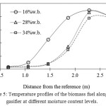 |
Figure 5: Temperature profiles of the biomass fuel along the gasifier at different moisture content levels. |
Not surprisingly, the overall temperature profile of thehigher levels of moisture content (28 and 34% w.b.) is lower than that of 16% w.b.because of heat loss during moisture evaporation. The temperature kept stable at ~ 40-45 ºCuntil the position of 1.48m and then increased greatly between 1.48 and 2.28 m positions. The highest temperatures of 28% and 34% w.b. were found at the position of plasma torch installed, which were 850 and 800ºC, respectively.Although the temperature of higher moisture feedstockincreased much slower, the temperature inthe combustion zone was still high enough to generate heat for the adjacent zones. The temperature at the final stage (reduction zone) was approximately the same for all moisture levels of biomass.
Moisture content of the feedstock plays a very important role in the gasification process. The upper limit of the moisture content for downdraft gasification is usually no more than 20 %w.b.16 to keep the system operated efficiently. In fact, the use of a feedstock with high moisture content in this study is almost impossible because considerable heat is used to evaporate moisture from the feedstock itself, reducing the overall gasifier temperature. Consequently, the heat available is not sufficient to drive other gasification reactions. Similar finding was found by Sulaiman et al.,17 who revealed that gasifying oil-palm fronds with moisture over 20% w.b. in a traditional downdraft gasification system caused a considerable drop in gasifier temperature (~ 600ºC) and resulted inextinguishingthe flame at the flare.However, an additional supply of external heat using a plasma arc in this study can reduce the limit of the gasification process whenusinga feedstock with a high moisture content.
Characteristics of Syngas
In this experiment, the syngas flow rate and ash discharge rate were controlled at the same levels for all the moisture content levels, and were 220 (Nm)3 h-1and 5 wt%, respectively. It was found that the increase of the moisture content resulted in an increase in the feedstock consumption rate (Table 3). Across all moisture treatment conditions, the equivalence ratio, which is the ratio of the actual A:F ratio to the stoichiometric A:F ratio, is found to be almost similar with an average value of 0.26. This result allows for the comparison of the effect of the moisture content on syngas quality and gasification efficiency.
The syngas composition of gasified biomassat different moisture levels is shown in Table 3. It found that the syngas quality was substantially influenced by the moisture in biomass.The CO decreased ~ 28% when the moisture content increased from 16 to 34% w.b. The decrease in the CO concentration with an elevated moisture content may be attributed to the increase in the feedstock density which creates a pressure drop along the gasifier, causing less O2 to be available. When the O2 decreases, the CO decreases accordingly.7On the contrary, the H2 was found to increasewith an increase in moisture content of the biomass.This was expected because more water is available for the H2 producing reactions. Compared with the feedstock moisture content of 16% w.b., the concentration of H2increased by11.9% and 17.4% when the moisture of feedstockincreasedto 28and 34%w.b., respectively. The increased H2and decreased CO with respect to the moisture content of the feedstock is consistent with the experiments ofZainal et al.,18and Sharma.19
Table 3: Experimental results of the plasma–assisted gasification test.
| Parameter | Unit | Moisture content of feedstock (%wt., w.b.) | ||
| 16 | 28 | 34 | ||
| Syngas flow rate | Nm3/h | 216.40 | 215.50 | 218.00 |
| Equivalent ratio | – | 0.25 | 0.25 | 0.28 |
| LHV of fuel | MJ/kg | 14.54 | 12.12 | 10.92 |
| Feedstock consumption rate | kg/h | 109.90 | 132.35 | 129.60 |
| Ash discharge rate | kg/h | 5.52 | 5.53 | 5.51 |
| % | 5.02 | 4.17 | 4.25 | |
| Composition | dry basis | |||
| CO | % | 19.34 | 14.51 | 13.84 |
| H2 | % | 20.30 | 22.71 | 23.83 |
| CH4 | % | 3.30 | 2.37 | 2.08 |
| O2 | % | 0.61 | 0.48 | 0.63 |
| CO2 | % | 13.03 | 15.10 | 14.80 |
| LHV | MJ/Nm3 | 5.80 | 5.12 | 5.05 |
| Syngas yield | Nm3/kg | 1.97 | 1.63 | 1.68 |
| Energy yield | MJ/kg | 11.42 | 8.34 | 8.49 |
| Energy input (Fuel) | MJ/h | 1,597.95 | 1,604.08 | 1,415.23 |
| Energy input (Plasma Power) | MJ/h | 129.60 | 129.60 | 129.60 |
| Energy output (Syngas Energy) | MJ/h | 1,255.12 | 1,103.36 | 1,100.90 |
| Cold-gas efficiency (ηcg) | % | 72.66 | 63.63 | 71.34 |
Considering the calorific value (LHV) of the syngas, it reduced slightly when the moisture content of feedstockincreased. Although the calorific value decreased with the increased in moisture content, it wasstill high enough for use as fuel for a gas engine, which requires a minimum energy of approximately 4.2 MJ (Nm)-3.15The difference between the low and high moisture contents in the calorific value may be mainly attributed to the variation of the temperatures available for reactions in the gasifier. It can be explained by the fact that the high temperature from plasma causes large amounts of radicals, electrons, ions, and excited molecules, thus increasing the rate of reactions and producing more quality syngas.13However, this phenomenon is demolished by an elevated moisture content.
System Performance Evaluation
The performance of the plasma-assisted gasification for the Giant Leucaena fuel at varying moisture contents is presented in Table 3. For each run, the plasma energy input was maintained at ~130 MJh-1 or ~ 76% of maximum capacity. The syngas yield was found to decrease with the increased moisture contentwith approximately 15% reduction. The decrease in the syngas yield is ascribed to the increase in the feedstock consumption rate from 109.90 to 129.60 kgh-1. The energy yield, which was calculated as the ratio of syngas energy to its corresponding consumption mass, also showed a similar trend. It reduced considerably by 27% for the same range of moisture content.
The cold gas efficiency (ηcg) is used to determine the energy efficiency of a gasification process. It was found that when the moisture content of feedstock increased from 16 to 28% w.b., the ηcgreduced by 9.03%. This is expected because partial heat is used to evaporate moisture, thus less heat is available for promoting endothermic gasification. However, the ηcgincreased when the moisture content of feedstockincreased from 28% to 34% w.b., which is close to that at 16% w.b.(~ 71.34%). This isdue to the heating value of feedstock at 34% w.b.,which was less than that of lower moisture content.
In general, drying process must be consideredfor high-moisture biomass prior toits use in a conventional gasification system. For Giant Leucaena,Arjharn20 found that the drying process using a rotary dryerrequired specific energy consumption (SEC) of 13.89 MJ (kgevaporated water)-1. If the energyrequired to reduce moisture content from 34 to 16% w.b. is taken into account, the overall energy efficiency of conventional gasification system is 55.62%. However, at the same initial moisture content of 34% w.b., the overall energy efficiency of gasification system can increaseup to71.34% with an assistance of plasma heat. This confirms that the use of plasma-assisted conventional gasification can reduce steps and energy in the biomass preparation, thus increasing overall system efficiency.
Tar and Dust Contents
Tar and dust play a crucial role in thegasification process and subsequent applications. They lead toblocking and fouling of downstream applicationssuch as turbines and engines.21Table 4 shows the effect of moisture in biomass fuel on tar and dust during plasma-assisted gasification. A variation on tar and dust contents was found with varied moisture content. The tar was found with a low content ranging from 2.97 to 3.32 mg (Nm)-3 for the biomass tested. The dust content of the lowest moisture level of 16% w.b. was higher than the others. Normally, the amount of tar and dust from gasification is 50-500 mg (Nm)-3.4Nonetheless, it depends on material specifications, working condition design and collecting as well as analysis.22Moreover, the performance of removing tar and dust depends on the composition and amount of tar and dust as well as the gas cleaner used.23For the experiment, results confirmthat plasma-assisted gasification system producedsyngas that is lower than the maximum limit for an internal combustion engine suggested by Bhattacharya et al.,12 andQuakk et al.15
Table 4: Tar and dust contents with respect to feedstock moisture content.
| Moisture Content | Impurity (mg/Nm3) | ||
| (%wt., w.b.) | Tar | Dust | Total |
| 16 | 3.11 | 85.27 | 88.38 |
| 28 | 2.97 | 62.56 | 65.53 |
| 34 | 3.32 | 68.88 | 72.2 |
Conclusions
Biomass at varying moisture levels between 16 and 34% w.b. was used to produce syngas using a pilot-scale downdraft gasification power plantwith an external heat of plasmaarc. The result showed that moisture affected the temperature in the gasifier. When the moisture of the biomass fuel increased, the temperature level in the reactor decreased obviously.However, the temperature in the combustion zone was high enough for gasification process. Furthermore, itaffected the gas produced, especially CO and H2concentrationsin the syngas, causing a variation of calorific value.The tar and dust content is acceptable for the downstream applications (< 88.4 mg (Nm)-3).The system performance of plasma-assisted gasification system presented in terms of cold-gas efficiency was found to range between 63.63 and 72.66% atvarying moisture contents, which is in the same range of conventional gasification system. Overall, it shows that plasma-assisted gasification can reduce limit of biomass utilization in terms of moisture content. Moreover, it can reduce steps and energy required for preparing biomass feedstock.
Acknowledgments
The authors would like to acknowledge the financial support given by the Office of Research and Project Coordination, Office of the National Research Council of Thailand, Energy Policy and Planning Office, Ministry of Energy, Thailand and Institute of Research and Development, Suranaree University of Technology, Thailand.
References
- Chingulpitak,S. andWongwises,S., Renewable and Sustainable Energy Reviews. 2014, 31, 312-318.
CrossRef - Arjharn,W.;Hinsui,T.;Liplap,P.andRaghavan,G.S.V.Journal of Biobased Materials and Bioenergy. 2012, 6, 1-11.
- Higman,C. andVan der Burgt,M. Gasification (2nd ed),Gulf Professional Publishing, Oxford, UK,2008.
- Kaupp,A. andGoss,J.R.State of art for small scale (50 kW) to gas producer-engine systems. United States Department of Agriculture, United States Forest Service: Washington, D.C. 1981.
- Susastriawan,A.A.P.;Saptoadi,H. andPurnomo.Renewable and Sustainable Energy Reviews.2017, 76, 989-1003.
CrossRef - Han,J. and Kim,H.Renewable and Sustainable Energy Reviews.2008,12, 397-416.
CrossRef - Hinsui,T.;Arjharn,W.;andLiplap,P.Suranaree J. Sci. Technol. 2015, 22, 183-196.
- Rutberg,Ph.G.;Bratsev,A.N.;Kuznetsov,V.A.;Popov,V.E.;Ufimtsev,A.A. andShtengel,S.V.Biomass and Bioenergy.2011, 35, 495-504.
CrossRef - Hlina,M.;Hrabovsky,M.;Kopecky,V.;Konrad,M. andKavka,T.Czechoslovak Journal of Physics. 2006, 56, 1179-1184.
- Zhang,L.;Xu,C.C. andChampagne,P.Energy Conversion and Management. 2010, 51, 969-982.
CrossRef - Arjharn, W.;Hinsui, T.;Liplap, P. andRaghavan, G.S.V. Energy Fuels.2013, 27, 229-236.
CrossRef - Bhattacharya, S.C.;Hla, S.S. andPham, H.L.Biomass and Bioenergy.2001,21, 445-460.
CrossRef - Janajreh, I.;Raza, S.S. andValmundsson, A.S.Energy Conversion and Management. 2013, 65, 801-809.
CrossRef - McKendry, M.Bioresource Technology.2002. 83, 37-46.
CrossRef - Quakk, P.;Knoef, H. andStassen, H. Energy from biomass: A review of combustion and gasification technology. World Bank Technical.1999, 422.
- Rajvanshi, A.K.in Alternative Energy in Agriculture, EditedY.D. Goswami, CRC Press,1986,2, 83-102..
- Sulaiman, S.A.;Atnaw, S.M. andMoni, M.N.Z.International Journal of Technology.2012. 3, 35-44.
- Zainal, Z.A.;Rifau, A.;Quadir, G.A. andSeetharamu, K.N.Biomass and Bioenergy.2002, 23, 283-289.
CrossRef - Sharma, A.K.Energy Conversion and Management. 2008, 49, 832-842.
CrossRef - Arjharn, W. Study of a small-scale biomass power plant for rural communities (phase II). National research council of Thailand, Bangkok.2007.
- Cao, Y.;Wang, Y.;Riley, J.T. andPan, W.Fuel Processing Technology.2006, 87, 343-353.
CrossRef - Devi, L.;Ptasinski, K.J. and Janssen, F.J.J.G.Biomass and Bioenergy.2003,24, 125-140.
CrossRef - Phuphuakrat, T.;Nipattummakul, N.;Namioka, T.;Kerdsuwan, S. andYoshikawa, K.Fuel. 2010, 89, 2278-2284.
CrossRef

This work is licensed under a Creative Commons Attribution 4.0 International License.


