Development trends in Conductive Nano-Composites for Radiation Shielding
Vishal Udmale*, Deepak Mishra, Ravindra Gadhave, Deepak Pinjare, Ramesh Yamgar
1*Ismail Yusuf College, Jogeshwari (E.), Mumbai-60 2Institute of chemical technology, Matunga, Mumbai-1
DOI : http://dx.doi.org/10.13005/ojc/290310
Article Received on :
Article Accepted on :
Article Published : 28 Oct 2013
Our paper reviews the use of conductive polymer composite materials in various applications for semi conductive, static-dissipative, anti-corrosive, electromagnetic interference (EMI) shielding and stealth composite coatings. The composite consists of conductive fillers and the insulating polymer network. The composite becomes electrically conductive as the filler content exceeds a certain critical value, generally called as Percolation Threshold Value (PTV). The PTV for a particular polymer composite can be drastically reduced by using nano-sized conductive fillers. The higher the aspect ratio (length:width) of the nano-fillers, the lower is the concentration for achieving the PTV. Traditionally the metals, carbon-black particles and alloys have been used as electrically conductive fillers; however, very high level of these fillers can be detrimental for the process ability, surface quality of the material, density, the cost and mechanical properties of the composite. By the use of nano conductive fillers, good conductivity will be achieved while retaining the original properties. Recently, one and two dimensional nano-creatures based on carbon such as carbon nanotubes and graphene respectively have received significant attention, due to their outstanding thermal, electronic and mechanical properties. In this paper we have compared different conductive filler materials, their dispersion techniques, and compatibility in polymer matrix and suitability in various above mentioned applications. The proliferation of mobile towers and electronic devices in the world results in harmful EMI and radio frequency interference (RFI) ultimately causing operational malfunction to electronic devises and also harmful to living beings, signifies the importance of this detailed review for EMI/RFI shielding applications.
KEYWORDS:Conductive nano-fillers;Polymer nano-composites;Electromagnetic interference (EMI) shielding;Radio-frequency interference (RFI) shielding;shielding efficiency (SE) measurement.
Download this article as:| Copy the following to cite this article: Udmale V, Mishra D, Gadhave R, Pinjare D, Yamgar R. Development trends in Conductive Nano-Composites for Radiation Shielding. Orient J Chem 2013;29(3). doi : http://dx.doi.org/10.13005/ojc/290310 |
| Copy the following to cite this URL: Udmale V, Mishra D, Gadhave R, Pinjare D, Yamgar R. Development trends in Conductive Nano-Composites for Radiation Shielding. Orient J Chem 2013;29(3). Orient J Chem 2013;29(3). Available from: http://www.orientjchem.org/?p=276 |
INTRODUCTION
By definition, a composite material is made of two or more constituents with significantly different physical and chemical properties and which remain separate and distinct within the final structure. This combination (hopefully) leads to a synergy of structural (e.g. mechanical) and/or functional (e.g. electronic, optical, etc.) properties compared to each constituent separate. These constituents of a composite can be classified in two categories: the matrix, i.e. the dispersing or continuous phase and the reinforcement, i.e. the dispersed phase. Because of the large variety of types of matrices (metallic, inorganic, polymeric, etc.) and dispersed phases (fibres, particles, crystals, etc.), the design potential of composite materials is extremely large[1].
Nanocomposite is a composite for which at least one of the dimensions of the dispersed phase is in the nano-meter range. Even if the term “nanomaterials” or “nanocomposites” appeared at the end of the decade eighties, the practical use of this type of materials is much older. The tremendous potential filler-matrix interface, combined with the same size of the components of the dispersed phase, makes this type of nano-composites very attractive, since they are expected to require much lesser amounts of filler to obtain similar or even better levels of performance (in regards to mechanical, thermal and electrical properties) [2].
The proliferation of electronic/ wireless devices in the world has caused Electromagnetic Interference (EMI) and Radio Frequency Interference (RFI) to become important concerns. Although majority of the electronics emit electrical and magnetic energy, if this energy unintentionally interacts with another device and causes it to malfunction, then it is considered as ‘interference’. EMI shielding has become a more significant issue due to the increased use of plastic housings for electronic equipment. Devices that are vulnerable to interference, such as micro-processors, computers, measuring instruments, broadcasting receivers, and navigation systems must often be shielded to protect them from the effects of EMI. All electromagnetic waves consist of two essential components, a magnetic field (H) and an electric field (E). These two fields are perpendicular to each other and the direction of propagation of wave is at right angles to the plane containing the two components. As shown in Fig. (1)
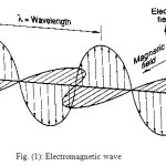 |
Fig. (1): Electromagnetic wave: Click here to View figure |
The relative magnitude depends upon the waveform and its source. The ratio of E to H is called wave impedance. The intrinsic impedance of free space is 377 Ω. EMI shielding consists of two regions, the near field shielding region and far field shielding region. When the distance between the radiation source and the shield is larger than λ/2π (where λ is the wavelength of the source), it is in the far field shielding region; whereas when it is less than λ/2π, it is near field shielding region [3].
The EMI/ RFI not only causes operational malfunction of electronic devises, but also is harmful to human health under certain circumstances. Radiations are widely used in each and every phase of life. Different phases of applications of electromagnetic radiations include mobile communication, radio communication, RADAR, wireless communication, different scanning methods in medical field, security applications and cooking microwave ovens. A lot of researches are in progress to find the possible health hazards associated with the electromagnetic radiation. There is evidence that at the frequencies used in mobile phone technology, children will absorbs more energy per Kg of body weight from an external electromagnetic field than adults. Because of the complexity and non-homogeneous nature of different living cells, it is very much difficult to completely characterize the propagation and predict the reaction of EM waves through human body. The magnetic and electric fields of electromagnetic radiation may cause thermal and non-thermal effects to human cells/ tissues.
- Non-thermal effect: Effect on the action of Genes and carcinogenicity. Many diseases such as leukemia, breast cancer, miscarriages are correlated to continuous exposure to EM fields and pulses. It was observed that, in human being these radiations directly affect the secretion of hormone ‘Melatonin’ during night time. The primary function of melatonin is scavenging harmful free radicals from the blood stream which may cause damage to DNA & tissues. Thus, The World Health Organization has classified radiofrequency electromagnetic radiation as a possible group 2b carcinogen [4,5].
- Thermal effect: When the electromagnetic wave penetrates through human body the energy is absorbed and it produces a heating effect. The mobile ionized species in the cells of human body influenced by electric field and vibrates in accordance with the frequency of oscillating electric filed. Which will produce an electric current and the electric resistance produced by the rest of the material will generate heat. Talking on Mobile Phone for prolong time will cause significant heating effect in the head even though our body tries to control it, by flowing the blood from other parts of the body [6].
Effective shielding is in critical demand to protect the environment, workplace and devises from EMI/ RFI. It is particularly needed for the buildings containing power transformers, mobile towers and other electronic facilities which will radiate electromagnetic wave to the surrounding.
EMI shielding is very much related to the protection against electrostatic discharge (ESD) or Surges in electric devices and connections. ESD is the uncontrolled transfer of static charges between two objects with different electrical potential. For the protection against ESD or Surges protection, surface conductivity of the shield is important, to allow a controlled and fast discharge or desiccation of static charges. Radar-absorption materials (RAM) have a growing and widespread applications in television and broadcasting, radar technology and microwave dark-room. Particularly in military applications, stealth weapons exhibit crucial effect during war. The research of RAM has also been accelerating with the stealth technology and significant progresses have been achieved till date. [7].
Most plastics are insulators from which electromagnetic waves can pass freely and the conductive barriers must be applied as shields to block the waves. To provide shielding, the substrate is coated with a conductive layer or the substrate material which itself is conductive. Conductive paint, metal foil, spray zinc, electroplating, vacuum metalizing, carbon-matrix composites and conductive blends of nano-structured polymer-clay composite, etc. are the methods for shielding against these threats. The coating method is much more common because it is easier to accomplish.
DEVELOPMENT TREND OF CONDUCTIVE COATINGS
Most EMI/ RFI suffered substrates such as plastics and rubbers are insulators (having resistivity in the range of 1015–1018 Ω cm), so electromagnetic waves can pass through them freely and conductive barriers are needed as shields. It is observed that the high conductivity and dielectric constant of the materials contribute to high EMI shielding efficiency (SE) [8,28]. The coating method is much more common because it is easier to accomplish.The advanced materials used as EMI, RFI, RAM include nano-metals, alloys, nano-oxides, nano-ferrite, nano-SiC, nano-SiC, nano-SiN, nano-graphite, conductive polymers, carbon nanotubes (CNTs) and Graphene.
The sequential development trend observed in EMI/ RFI shielding, RAM are given bellow-
- Metal Coating
Metals are excellent conductors of electricity and can absorb, reflect or transmit electromagnetic interference. Due to high electrical conductivity of Iron group metal nanoparticles (in order of magnitude 106S cm-1); they are particularly suitable as shielding material against electromagnetic fields. Several of the metals are available off the shelf, in the form of sheet stock form thickness of about 0.4 mm or less to about 32 mm or more. Metals having thickness less than 0.4 mm are considered as foils. Many of the metals with high permeability come in foil thickness ranging from about 25.4 µm to 254 µm. They are also available in tape form. Coating on plastics are well established techniques for decorative, automotive appliance and plumbing products.
The different coating techniques are:
- Foil laminates and tapes
- Ion plating
- Vacuum metallization
- Zinc flame spraying
- Zinc arc spraying
- Cathode sputtering
- Conductive paints
- Electroless plating
- Electroplating
It also has several drawbacks as it required pre-treatment on the substrate to be coated and required special equipment and thus are costlier; on the other hand they also have limited natural stability and heavier [8, 29].
- Conductive polymers
Conducting polymer are highly delocalized π-electron system with alternate single and double bonds in the polymer backbone. The electronic conduction in conjugated systems occurs via process known as doping either with electron acceptors or donors. This doping process creates the band structure to enhance their conductivity by many orders, whereas undoped conjugated polymers are semiconductors with band gaps ranging from 1 to 4eV; therefore their room temperature conductivities are very low, typically of the order of 10−6 S m −1or lower. Hexanoic acid (HA)is a dopant used to improve the conductivity of Polyaniline (PANI). Polyacetylene, is the simplest poly-conjugated system, which can be made conductive by reaction with Br2 or I2 vapors. The highest value reported to date has been obtained in iodine-doped polyacetylene (>15 S cm −1) [9]. PANI is perhaps the most versatile as EMI shield because of its desirable properties, such as chemical and thermal stability, controllable conductivity and high conductivity at microwave frequencies [10, 11, 26].
- Metal filled polymer composites
Insulating polymer matrix can be made conductive by incorporation of metal (stainless steel, Ag, nickel, etc.) powder or fibres as conducting filler in a polymer matrix. However, there are a few drawbacks to using metal as a shielding material. The weight of the ‘heavy’ metal can be an issue in the case of full metal shielding and plastic matrices with high metal filler content, especially in applications where mass should be as low as possible. Furthermore, dispersed metal particles are easily oxidized/ corrode especially in water-based systems. In order to produce metal coatings, at least two step processing technique have to be used – one for the support and one for the coating – which can be costly. It is also difficult to apply these coatings onto complicated or irregular surfaced objects. In addition, the long-term adhesion of the coating to the support has to be reliable. The combination of the magnetic nanoparticles and conducting polymer leads to formation of ferromagnetic conducting polymer nano-composite which possesses unique combination of both electrical and magnetic properties from respective materials plus some additional benefits. This property of the nanocomposite can be used an electromagnetic shielding material since the electromagnetic wave consist of an electric (E) and the magnetic field (H) right angle to each other. The ratio over E to H factor (impedance) has been subjugated in the shielding purpose. The conducting and ferromagnetic type of materials can effectively shield electromagnetic waves generated by an electric source, whereas electromagnetic waves generated from a magnetic source can be shielded effectively only by magnetic materials [12, 13].
- Core shell metal and its polymer composites
The potential applications of these metallic iron-group NPs are limited, since they were easily oxidized in air or moisture and fast dissolve in acidic conditions. The easy and rapid oxidation/dissolution of the NPs is due to the large specific surface area. In order to address this challenge, several approaches have been investigated. The most widely reported approach is to coat the iron-group metal cores with a three types of protective shells such as noble metal, insulator/metal oxide [e.g. carbon, silicon oxide (SiO2), zirconia (ZrO2)] and conductive polymers. The reported iron-group NPs with a protective shell include carbon coated Co, Ni and Fe; silica coated Co, Fe, Fe3O4 and Fe–Ni alloy; NiO coated Ni; ZrO2 coated Fe; iron oxide coated Fe; Au coated Fe/Co, Pt, Pd, Cu, alumina (Al2O3), yttria (Y2O3) or silver coated iron group metal NPs. The wide potential applications of the core–shell nanoparticles are predicted and are currently limited by the availability of large quantities of these multifunctional nanoparticles [14].
- CNT/Polymer composites
Since the discovery of CNTs and its reliable characterization, they have been the object of frenetic and intense research. CNTs are emerging as the prototypical electronic one-dimensional conductor due to the delocalization of the π-electrons along their wall. CNTs have a unique electronic character, ranging from high-conductivity metallic behavior to semiconducting with a large band gap, depending on its ‘Chirality’. Being covalently bonded, as electrical conductor they do not suffer from electro migration or atomic diffusion and thus can carry high electron densities (107 – 109 A/cm2).A large part of the CNT/polymer based composites exploit CNTs as conductive filler dispersed into an insulating matrix [15]. It’s very low electrical PTV allows one to obtain, with only very small amounts of CNTs, an electrical conductivity sufficient to provide an electrostatic discharge (e.g. In epoxy-SWCNT composite percolation threshold at 0.062 wt. % SWCNTs is obtain by Li et al. in the year 2006). By adjusting the type and amount of CNTs dispersed in the polymer matrix, plastics exhibiting tuneable levels of conductivity can be produced for various applications. The first commercial applications for Multi walled CNTs by ‘Hyperion Catalysis International’, who make use of CNT’s properties to address electrostatic discharge. Applications of these range from electronics to aerospace sectors, such as electrostatic dissipation, EMI shielding, multilayer printed circuits to transparent conductive coatings. These have found use in the automotive industry in conductive nylon for fuel lines, connectors and fuel filter housings, as well as in exterior plastic parts that must be conductive in order to permit their electrostatic spray painting. It is an ideal constituent to develop cheap, light and easy-to-process “conductive plastics”, for future applications where metals and/or semiconductors are used. For ESD for example, the conductivity of the nanocomposite should be between 10-10 and 10-3 S m −1. On the other hand, for electromagnetic shielding applications, the electrical conductivity range should be higher than 1 S m −1. When the conductivity is higher than 10-3 S m −1, the materials are considered as (semi-)conductive [16, 17, 18].
- Graphene/polymer composites
Graphene is a one-atom-thick planar sheet of sp2 -bonded carbon atoms arranged in a hexagonal lattice. It is believed to be the “thinnest and strongest material in the universe” and predicted to have remarkable physical and chemical mechanical, electrical, thermal and microwave absorption properties. A frequently cited property of graphene is its electron transporting capacity. This means that an electron moves through it without much scattering or resistance. It has high electron mobility at room temperature i.e. 200 000 cm2V−1 s–1. Its electrical conductivity is much higher than that of ‘Cu’, but its density is almost four times lower. This makes graphene potentially more favourable for improving the properties of polymer matrices. More importantly, graphene is much cheaper than CNTs, because it can be easily derived from a graphite precursor in large quantity. It has a higher surface-to-volume ratio compared to CNTs because in CNTs the inner nanotube surface is inaccessible to polymer molecules. A theoretical study has shown that graphene filled composites have slightly lower percolation threshold and higher electrical conductivity and critical exponent, and can form conductive networks more easily than CNT-filled composites at the same volume fraction of fillers (e.g.PTV of 0.0025 wt. % CNTs in epoxy reported by Stankovich et.al.).The effective complex permittivity and EMI shielding effectiveness in the frequency range from 8.2 to 18 GHz. Results show that graphene/polymer composites are much more easily processable and provide a higher shielding effectiveness over the whole frequency range than that with CNTs filled composites [19, 20, 21].
PROCESSING REQUIREMENTS IN SYNTHESIZING NANOCOMPOSITES
Formation of a conductive, three-dimensional network of the conductive filler in the continuous polymer phase is desired aspects for fulfilling all the previously mentioned claims. The three main strategies for dispersion of nano-metals, -metal oxides are direct mixing of the filler and the matrix, mixing with the help of a third component that partly or integrally remains at the filler-matrix interface and modification of one of the two components (filler or matrix) of the nanocomposite in order to favor their interactions and thus the quality of the interface filler-matrix.
The traditional routes to prepare nano-composites of layered/tubular compounds as reinforcement material especially clays, CNTs & Graphene etc. can be summarized as follows [22, 27];
- In situ intercalative polymerization
Polymer is formed (initiation of polymerization by heating or radiation or by diffusion) between thelayers by swelling the layer hosts within the liquid monomer or monomer solution
- Melt intercalation
This method is environmentally benign one. It uses all types of polymers as well as compatible with practicing polymer industrial processes such as injection molding. Thus it is most popular procedure to prepare nano-composites for industrial applications. In this method, polymers and layered/ tubular fillers are annealed above the softening point of the polymer.
- Intercalation of pre-polymer from solution
The layered host is to be swelled in a solvent (water, toluene, etc.) followed by its mixture with polymeror pre-polymer, whereby the chains of the latter intercalate while displacing the solvents used for swelling. Polymer layered/ tubular nanocomposite results when the solvent within the interlayer is removed.
- Exfoliation/adsorption
First the layered host is exfoliated in a solvent, in which the polymer is soluble (water, toluene, etc). The polymer is adsorbed onto the single-layer surfaces and after evaporation of the solvent or a precipitation procedure the single layers are restacked, resultantly trapping the polymer and the hydrated/ solvated ionic species.
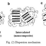 |
Fig. (2) Dispersion mechanism Click here to View figure |
All the above methods of dispersion of nano-fillers in to polymer matrix obviously required high mechanical shear force for intercalation & exfoliation, which can be supplied through Ultra-sonicators, Extruders, Ball mills, High speed dispersers etc.
MECHANISM OF EMI SHIELDING
- The primary mechanism of EMI shielding is usually reflection of the radiation by the shield. The shield must have free charge carriers (electrons or holes) which interact with the EMF. As a result, the shield tends to be electrically conducting, but a high conductivity is not required, a volume resistivity of the order of 1 Ωcm is typically sufficient for EMI shielding purpose.
- A secondary mechanism of EMI shielding is absorption. For significant absorption of the radiation, the shield should have electric as well as magnetic dipoles which can interact with the electromagnetic fields in the radiation. Thus, having both magnetic and conducting components in a single system, such materials can be used for an EMI shielding. e.g. Ferrite compounds.
- The third mechanism of EMI shielding is multiple reflections within the interlayer of MWCNTs.
All the three mechanisms are shown in following Fig.(3)[22].
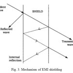 |
Fig. 3. Mechanism of EMI shielding Click here to View figure |
TECHNIQUES FOR CHARACTERIZATION OF POLYMER NANOCOMPOSITES
Experimental techniques used for the characterization of nano-composites include-
NMR for materials behaviour (giving greater insight into the surface chemistry, morphology and to a very limited extent the quantification of the level of exfoliation in polymer nano-composites), XRD (due to ease and availability), transmission electron microscopy (TEM—allows a qualitative understanding of the spatial distribution, internal structure, of the various phases, direct visualization of defect structure and a detail topography), differential scanning calorimetry (DSC—to understand the nature of crystallization taking place in the matrix), FTIR (to detect functional groups in polymer backbone and bonding agent on fillers ) and resonance Raman spectroscopy (for structural studies). The atomic force microscope (AFM) is high magnifying imaging equipment to study topography of nano-composites surfaces and interfaces.
MEASUREMENT OF SHIELDING EFFECTIVENESS (SE)
Shielding effectiveness is a measure of the performance of the shield. The measurement devise consist of Network Analyzer, which is capable of measuring insertion loss and return loss. Following are the four test methods commonly used to measure EMI/ RFI Shielding and effectiveness of a shielding material.
- Open Field or Free Space Method: It uses to evaluate the practical shielding effectiveness of a complete electronic assembly. This is a true test of the service performance of the designed shielding of the finished product. In this test, devise is kept at distance of 30 m from the receiving antenna which records the radiated emission.
- Shielded Box Method: It widely used for comparative test of SE of different shielding materials. In this method receiving antenna is inside the metal box having window coated with specimen sample, whereas the transmitting antenna is at outside the box. As shown in Fig. (4)
- Shielded Room Method: Is the most sophisticated one. The general principle is the same as the shielded box method except that each of the components of the measuring system, signal generator, transmitting antenna, receiving antenna and recorder are isolated in separate rooms to eliminate the possibility of interference.
- Coaxial Transmission Line Method: It is the most preferred and precise one and is carried out on small doughnut shaped samples chamber a sow in Fig. (5). The American Society for Testing and Materials, ASTM D4935-99, has adopted coaxial transmission line technique [23].
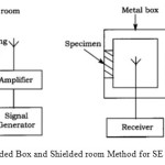 |
Fig. (4) Shielded Box and Shielded room Method for SE measurement Click here to View figure |
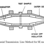 |
Fig. 5. Coaxial Transmission Line Method for SE measurement Click here to View figure |
The effectiveness of a shield and its resulting EMI attenuation are based on the frequency, the distance of the shield from the source, the thickness of the shield and the shield material. Shielding effectiveness (SE) is normally expressed in decibels (dB) as a function of the logarithm of the ratio of the incident and exit electric (E), magnetic (H), or plane-wave field intensities (F):
SE (dB) = 20 log (Ei/Et),
SE (dB) = 20 log (Hi/Ht),
SE (dB) = 20 log (Fi/Ft), respectively.
Where,
Ei, Hi and Fi are the electric, magnetic and plane wave field intensity incident on the shield
Et, Ht and Ft are the counterparts transmitted through the shield
The total SE of a shielding materialequals the sum of the absorption factor (SEA), the reflection factor (SER) and the correction factor to account for multiple reflections (SEM) in thin shields
SE = SEA + SER + SEM
All the terms in the equation are expressed in dB. The SEM, can be neglected if the absorption loss SEA is greater than 10 dB. In practical calculation, SEM can also be neglected for electric fields and plane waves.
For a material to have a high SE it must exhibit a high conductivity and in order to have a low internal reflection, it must have a low dielectric constant. A shielding effectiveness of 30 dB, correspondingto 99.9% attenuation of the EMI radiation, is considered an adequate level of shielding for many applications [3, 24, 25].
CONCLUSION:
The effect of growth of electronic industry and its widespread use of electronic equipment in communications, computations, automations, biomedical, space and other purposes has led to many EMI/ RFI problems to the designers as their systems/subsystems operate in close proximityand even to the safety and health of living beings. It clearly implies that the EMI shielding materials, surge/ transient suppressors and EMI filters plays an important role in controlling EMI in equipment and systems. Polymer-based nano-composite EMI shielding materials that add EMI shielding efficacy can provide significant weight savings as well as resistance to corrosion and other environmental degradation. This review highlights the importance and necessity of use, particularly of conducting nano-composites for the shielding of EMI/RFI.
REFERENCES
- Hussainet. al., Polymer-matrix Nanocomposites: An Overview; Journal of Composite Materials (2006), 40, 17
- William Gacitua E., Aldo Ballerini A.,Jinwen Zhang; Polymer nanocomposites: synthetic and natural fillers a review; Maderas. Ciencia y tecnología (2005); 7(3): 159-178.
- S. Geetha, K. K. Satheesh Kumar,Chepuri R. K. Rao,M. Vijayan,D. C. Trivedi; EMI Shielding: Methods and Materials—A Review; Journal of Applied Polymer Science (2009); 112, 4, 2073-2086
- Press release- N 208;International agency for research on Cancer, WHO; 31st May, 2011
- Harland JD, Liburdy RP; “Environmental magnetic fields inhibit the antiproliferative action of tamoxifen and melatonin in a human breast cancer cell line“; Bioelectromagnetics (1997); 18 (8): 555–562
- Recent advances in research on Radio frequency Fields and Health:
2001-2003, A follow-up to The Royal Society of Canada - Xiao-Gang Sun, Ming Gao, Cheng Li and Yiqiang Wu; Microwave Absorption Characteristics of Carbon Nanotubes; Carbon Nanotubes – Synthesis, Characterization, Applications, chapter 13
- Genaro A. Gelves, Mohammed H. Al-Salehand UttandaramanSundararaj; Highly electrically conductive and high performance EMI shielding nanowire/polymer nanocomposites by miscible mixing and precipitation; J. Mater. Chem. (2011) 21, 829-836
- Shirakawa, H. Louis, E. J. MacDiarmid, A. G. Chiang, C. K. Heeger;Synthesis of Electrically Conducting Organic Polymers; A. J. J ChemSocChemCommun(1977), 578
- Dr.Eddy Brinkman; Electromagnetic Shielding With Conducting Polymers(2009); 25-31; www.polycond.eu
- James Margolis; Conductive Polymers and Plastics; Chapman and Hall(1989);121
- S.K. Dhawan, Anil Ohlan and Kuldeep Singh;Designing of Nano Composites of Conducting Polymers for EMI Shielding Advances in Nanocomposites – Synthesis, Characterization and Industrial Applications, chapter 19
- White Sadie, Vemulkar Tarun, Fischer John, Winey Karen;Electrical Conductivity in Polymer Composites Containing Metal Nanowires;American Physical Society (2009), 19
- Suying Wei, Qiang Wang, Jiahua Zhu, Luyi Sun, Hongfei Line and ZhanhuGuo; Multifunctional composite core–shell nanoparticles; Nanoscale (2011); 3, 4474–4502
- Yong Li, Changxin Chen, Jiang-Tao Li; Enhanced Dielectric Constant for Efficient Electromagnetic Shielding Based on Carbon-Nanotube-Added Styrene Acrylic Emulsion Based Composite; Nanoscale Res Lett. (2010);5, 1170–1176
- Mohammed H. Al-Saleh, UttandaramanSundararaj; Electromagnetic interference shielding mechanisms of CNT/polymer composites; Carbon, 47 (2009), 1738 –1746
- Xiao-Gang Sun, Ming Gao, Cheng Li and Yiqiang Wu; Microwave Absorption Characteristics of Carbon Nanotubes;Nanchang University, Sun nanotech Co. Ltd; China
- Ho Chang, Yun-Min Yeh and Kouhsiu-David Huang; Electromagnetic Shielding by Composite Films Prepared with Carbon Fiber, Nis Nanoparticles, and Multi-Walled Carbon Nanotubes in Polyurethane; Materials Transactions(2010); 51, 6,1145-1149
- Hong S. K., Kim K.Y.; Electromagnetic interference shielding effectiveness of monolayer grapheme; Nanotechnology.(2012); 16, 23(45), 455704
- ParveenSaini and ManjuArora; Microwave Absorption and EMI Shielding Behavior of Nanocomposites Based on Intrinsically Conducting Polymers, Graphene and Carbon Nanotubes; New Polymers for Special Applications (2012), chapter 3
- D. Galpayaet al.; Recent advances in fabrication and characterization of graphene-polymer nanocomposites; Graphene (2012); 1, 30-49
- Y. Li et al.; Electrical conductivity and electromagnetic interference shielding characteristics of multi-walled carbon nanotube filled polyacrylate composite films; Applied Surface Science (2008); 254, 5766–5771
- Horacio Vasquez, Laura Espinoza, Karen Lozano; Simple Device for Electromagnetic Interference Shielding Effectiveness Measurement; IEEE (2009); 62 – 68
- W.J. Krzysztofik, R. Borowiec, B. Bieda; Some consideration on shielding effectiveness testing; Radioengineering (Dec 2011); 20, 4
- Zunfeng Liu, Gang Bai, Yi Huang; Reflection and absorption contributions to the electromagnetic interference shielding of single-walled carbon nanotube/polyurethane composites; (April 2007); 45, 4, 821-827
- L. W. Shacklette , N. F. Colaneri, V. G. Kulkarni; EMI shielding of intrinsically conductive polymers; Journal of Vinyl Technology; Journal of Vinyl Technology (June 1992);118–122
- SankaranS. ; Thermosetting polymer composites for EMI shielding applications; Electro Magnetic Interference and Compatibility (INCEMIC- 2006), 1 – 6
- Alan E. E. Rogers, PreethiPratap; Radio frequency interference shielding and mitigation techniques;Radio Science (October 2005); 40, 5
- Nan-I Liu, Roelof van der Meer; Synergistic effect of metal flake and metal or metal coated fibre on EMI shielding; US pat.( 1986) No. 4566990

This work is licensed under a Creative Commons Attribution 4.0 International License.


