Synthesis and Characterization of Chromium Oxide Nanoparticles
Vivek Sheel Jaswal, Avnish Kumar Arora*, Joginder Singh, Mayank Kinger, Vishnu Dev Gupta
Department of Chemistry, Maharishi Markendeshwer University, Mullana -133207, (Haryana), India.
DOI : http://dx.doi.org/10.13005/ojc/300220
Article Received on :
Article Accepted on :
Article Published : 10 Jun 2014
Chromium oxide nanoparticles (NPs)have been rapidly synthesized by precipitation method using ammomia as precipitating agent and are characterized by using X-ray Diffraction (XRD), Thermo Gravimetric Analysis (TGA), UV-Visible absorption (UV), Infrared Spectoscopy (IR), Scanning Electron Microscopy (SEM) and Transmission Electron Microscopy (TEM). XRD studies show that chromium oxide NP is formed as Cr2O3 and it has hexagonal structure. The shape and particle size of the synthesized Cr2O3 NPs is determined by SEM and TEM. The images showed that the size of NPs of Cr2O3 varied from 20 nm to 70 nm with average crystalline size 45 nm. UV-Visible absorption and IR spectoscopy confirm the formation of nanosized Cr2O3. TGA verifies that the Cr2O3 NPs are thermally stable upto 1000 °C.
KEYWORDS:Nanaoparticles; chromium oxide; TEM; metal oxides; XRD analysis.
Download this article as:| Copy the following to cite this article: Jaswal V. S, Arora A. K, Singh J, Kinger M, Gupta V. D. Synthesis and Characterization of Chromium Oxide Nanoparticles. Orient J Chem 2014;30(2). |
| Copy the following to cite this URL: Jaswal V. S, Arora A. K, Singh J, Kinger M, Gupta V. D. Synthesis and Characterization of Chromium Oxide Nanoparticles. Orient J Chem 2014;30(2). Available from: http://www.orientjchem.org/?p=3817 |
Introduction
Transition metal oxide NPs have many applications as catalyst [1-5], sensors [6-9], superconductors [10-11] and adsorbents [12-13]. Metal-oxides constitute an important class of materials that are involved in environmental science, electrochemistry, biology, chemical sensors, magnetism and other fields. Chromium oxides have attracted much attention recently because of their importance both in science and technology. As the chromium have different stable oxidation states, it can form the different types of oxides. Special attention has been focused on the formation and properties of chromium oxide (Cr2O3), which is important in specific applied applications such as in high temperature resistant materials[14], corrosive resistant materials[15], liquid crystal displays[16, 17], green pigment [18], catalysts[19,20] and so on. It is well known that intrinsic properties of inorganic materials are mainly determined by their composition, structure, crystallinity, size and morphology; great efforts have been devoted to the investigation of different Cr2O3 materials synthesis [21-23].
Various techniques have been developed to synthesize Cr2O3 NPs such as precipitation [24], precipitation gelation [25-27], sol gel [28-30], mechanochemical reaction, oxidation of chromium in oxygen [31] and sonochemical method [32]. Among all these methods as mentioned, chemical reduction in aqueous solvents exhibits the greatest feasibility to be extended to further applications in terms of its simplicity and low cost. In the present work we have reported the synthesis of Cr2O3 NPs by aqueous precipitation using ammonia as precipitating agent and Cr2(SO4)3 as the source of chromium. Khatoon et al [33] reported the internalization of Cr2O3 NPs in Escherichia coli cells by flow cytometry using light scattering method. El-ajaily et al [34] reported the antibacterial activity of Cr (VI) and Cr (III) complexes against P. aeruginosa bacteria. Ramesh et al synthesized nano-sized Cr2O3 by reduction of potassium dichromate solution with Arachis hypogaea leaf extract containing reducing sugars which act as reducing agent.
Ming Hua and co-workers [35] have studied the nano-sized metal oxides, including ferric oxides, manganese oxides, aluminum oxides, titanium oxides, magnesium oxides and cerium oxides, which provide high surface area and specific affinity for heavy metal adsorption from aqueous systems. Tanya Tsoncheva et al [36] prepared mesoporous ceria and SBA-15 silica with iron and Cr2O3 NPs. The simultaneous presence of iron and chromium oxides lead to change in their dispersion, providing easier reducibility, higher catalytic activity and stability of the obtained materials in comparison with the corresponding mono-component ones. P. Gibot and L. Vidal [37] prepared nanosized Cr2O3 by the common thermal decomposition of Cr(NO3)3·9H2O chromium (III) nitrate nonahydrate. These pristine Cr2O3 NPs, with a slightly sintered sphere-shaped morphology, exhibited a 10 nm particle size with a monocrystalline character as demonstrated by the TEM and XRD correlation. Grzegorz Lota et al [38] reported single wall carbon nanotubes (SWNTs) filled and doped with Cr2O3 used as attractive electrodes for super capacitors. Selvam Sangeetha et al [39] reported a predominant solid state route, wherein a chromium–urea complex prepared under solvent free conditions was calcined at high temperature to obtain Cr2O3 NPs. The evolution with calcinations of Cr2O3 NPs of catalytic interest, prepared from reduction of K2Cr2O7 with maleic acid, has been studied by S.M. El-Sheikh et al [40]. Lifang Chen et al [41] demonstrated that the Cr2O3 spheres show an exceptional ability to remove azo−dye pollutant in water treatment. Thus, the porous Cr2O3 spheres with very good dye absorptions are expected to be useful in alternative absorption technologies. As Cr2O3 NPs have wide applications in science and technology, an attempt has been made to synthesize Cr2O3 NPs by aqueous precipitation using ammonia as precipitating agent. This method involves a simple, cheap and one step process for the synthesis of Cr2O3 NPs. The obtained NPs of Cr2O3 have been characterized by XRD, TGA, IR, UV, SEM and TEM.
Methods and materials
Chemicals
All chemicals used in the experiment are analytic reagent grade. Chromium sulphate, Cr2(SO4)3 was purchased from Merck, India. Ammonium hydroxide (liquor ammonia) was purchased from SRL. Deionized water was used throughout the experiment.
Synthesis of Chromium oxide:
500 ml of 0.1M solution of Cr2(SO4)3 was taken and aqueous ammonia was added drop wise with constant stirring until the pH of the solution reached to 10. The precipitates thus obtained were filtered by Buckner funnel and was washed several times with distilled water. The precipitates were dried in oven at 70°C for 24 hrs and were calcined at 600°C in a muffle furnace for 5 hrs. Obtained material was ground and sieved through 100 mesh size sieve.
Characterization techniques
The microstructure of the particles was characterized by X-ray diffraction, Philips PW 11/90 diffractometer using nickel filtered CuKα (l = 1.5405 Å) radiations. The average diameter (D) of the Cr2O3 NPs has been calculated from the broadening of the XRD peak intensity after Kα2 corrections using the Debye-scherrer equation. Transmission electron microscopy measurements of the sample were taken on Hitachi H7500 with a 70 kV accelerating voltage. The dispersions of NPs in water were placed on carbon-coated 400 mesh copper grids, allowed to dry at room temperature before taking measurement. The obtained micrographs were then examined for particle size and shape. TGA study was carried out using Perkin Elmer Pyris Diamond. The UV-visible spectra of as-prepared aqueous solutions were taken by UV spectrophotometer (Perkin Elmer Lambda 25) in the wavelength range of 200–900 nm to determine the absorbance due to surface plasmon resonance (SPR) in the case of Cr2O3 NPs. The infrared spectra of adsorbents, adsorbates and adsorption adducts were recorded in KBr discs on a Perkin Elmer FTIR spectrophotometer (Model Perkin Elmer-1600 Series).
Table1: X- Ray Diffraction Data for Chromium Oxide (Cr2O3)
| S. No. | d= λ/2 SinΦ(Observed) | d= λ/2 SinΦ(Reported) | I/I0 × 100 %(Observed) | I/I0 × 100 %(Reported) |
| 1. | 3.62189 | 3.6210 | 63.22 | 62.90 |
| 2. | 2.65863 | 2.6625 | 80.55 | 80.50 |
| 3. | 2.47438 | 2.4760 | 100.00 | 100.00 |
| 4. | 2.17017 | 2.1035 | 36.34 | 33.05 |
| 5. | 1.81171 | 1.8045 | 27.53 | 27.50 |
| 6. | 1.46172 | 1.4585 | 17.36 | 17.25 |
| 7. | 1.42926 | 1.4300 | 31.84 | 30.99 |
| 8. | 1.29440 | 1.2830 | 9.80 | 9.70 |
| 9. | 1.08658 | 1.0565 | 9.18 | 9.00 |
Results and discussions
X-ray and IR studies
X-ray diffraction of synthesized oxide is shown in Fig.1. The X-ray diffraction plot, shows peaks only due to Cr2O3 and no peak is detected due to any other material or phase indicating a high degree of purity of the as-synthesized sample. The broadening of the X-ray diffraction lines, as seen in the Fig. 1 reflects the nano-particle nature of the sample. In X-ray diffraction, some prominent peaks were considered and corresponding d-values were compared with the standard. X-ray diffraction shows that the formed nano metal oxide is pure Cr2O3 and having hexagonal structure.
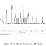 |
Figure1: X-ray diffraction for chromium oxide (Cr2O3) Click here to View Figure |
Sharpness of the peaks shows good crystal growth of the oxide nanoparticles. Average particle size (t) of the particles have been calculated using from high intensity peak using the Debye-Scherrer equation
t = Kλ/ B cos Φ
Where ‘t’ is the average crystalline size of the phase under investigation, ‘K’ is the Scherrer constant (0.89), ‘λ’ is the wave length of X – ray beam used, ‘B’ is the fullwidth half maximum (FWHM) of diffraction (in radians) and ‘θ’ is the Bragg’s angle. The average crystalline size calculated is 45 nm which is in close agreement with the TEM results.
IR spectra of synthesized Cr2O3 NPsshow peak due to M-O (Cr-O) stretching at 569.30 cm-1 and 632.61 cm-1. Peaks at 3436.08 cm-1 and 1631.32 cm-1may be due to the presence of moisture and carbon dioxide present in atmosphere [Fig. 2].
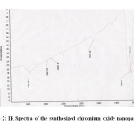 |
Figure2: IR Spectra of the synthesized chromium oxide nanoparticles.Click here to View Figure |
TGA and UV studies
TGA transition shows no considerable weight loss upto 10000 C [Fig. 3]. It simply indicates that when Cr2(OH) 3 is heated, it converts into Cr2O3 and it is thermally stable in nature and we can use these synthesized NPs upto 10000 C. Nanosized Cr2O3 particles show absorbance in the UV-visible region due to SPR, which originates due to the resonance of collective conduction electrons with incident electromagnetic radiations. It provides a sharp absorbance in the visible region around 460 nm [Fig. 4]. The shape of the resonance peak can be qualitatively related to the nature of NP. Small and uniform-sized NP with a narrow size distribution gives a sharp absorbance, whereas NP with a wide size distribution or any kind of aggregation shows a broad
absorbance [42-49].
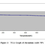 |
Figure 3: TGA Graph of chromium oxide NPSClick here to View Figure |
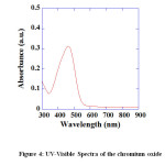 |
Figure4: UV-Visible Spectra of the chromium oxid.Click here to View Figure |
SEM and TEM studies
SEM study was carried out to find out the surface morphology of synthesized Cr2O3. SEM micrograph of the Cr2O3 NPs have been represented in Fig. 5.
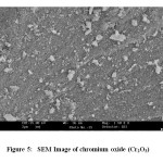 |
Figure 5: SEM Image of chromium oxide (Cr2O3)Click here to View Figure |
SEM study shows that the chromium oxide is in pure form and the particles are beautiful white colored nanoparticles. TEM study was carried out to find out exact particle size of synthesized Cr2O3 NPs. Fig. 6 shows the TEM images of the synthesized Cr2O3 NPs. TEM images show that Cr2O3 NPs are having particle size in the range of 20 nm – 70 nm [Fig. 6]. The size distribution histograms for NPs provided their respective sizes as 32.9 ± 13.3 nm [Fig. 7a], 32.2 ± 9.3 nm [Fig. 7b], 31.4 ± 9.5 nm [Fig. 7c], 28.8 ± 8.9 nm [Fig. 7d], respectively.
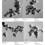 |
Figure6: TEM Images of chromium oxide (Cr2O3)Click here to View Figure |
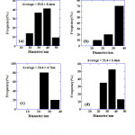 |
Figure7: Size Histograms of Figure 6Click here to View Figure |
Conclusion
Chromium oxide nanoparticles with hexagonal structure are synthesized successfully by aqueous precipitation method using ammonia as precipitating agent. From TEM study, it is found that particles are with average size of 20 – 70 nm. XRD studies show that chromium oxide was formed as Cr2O3 instead of the commonly formed CrO2. The chemical reduction approach addressed in the present work on the synthesis of Cr2O3 nanoparticles are simple, cost effective, eco-friendly. The resultant nanoparticles are highly stable and reproducible that exhibit the greatest feasibility to further applications in the process of stropping knives, glasses, inks, paints and precursor to the magnetic pigment.
References
- Xu J. Z.; Zhu J. J.; Wang H.; Chen H. Y.; Analytical Letters, 2003, 36, 2723-2733.
- Lv W. Z.; Liu B.; Luo Z. K.; Ren X. Z.; Zhang P. X.; Journal of Alloys and Compounds, 2008, 465, 261-264.
- Zhou W.; Wachs I. E.; Kiely C. J.; Current Opinion in Solid State and Materials Science, 2012, 16, 10-22.
- Altincekic T. G.; Boz I.; Aktürk S.; Journal of Nanoscience and Nanotechnology, 2008, 8, 874-877.
- Zhou J.; Song H.; Chen X.; Zhi L.; Yang S.; Huo J.; Yang W.; Chemistry of Materials, 2009, 21, 2935–2940.
- Yang M.; He J.; Hu X.; Yan C.; Cheng Z.; Zhao Y.; Zuo G.; Surface and Interface Physics papers in Physics, ASurface and interface Physics papers A, 2011, 155, 692-698.
- Segev-Bar M.; Haick H.; ACS Nano, 2013, 7, 8366–8378.
- Kuban P.; Berg J. M.; Dasgupta P. K.; Analytical Chemistry, 2004, 76, 2561–256.
- Sharma S. S.; Nomura K.; Ujihira Y.; Journal of Material Science, 1991, 26, 4104-4109.
- Pillai V.; Kumar P.; Hou M. J.; Ayyub P.; Shah D.O.; Advance in colloid and Interface Science, 1995, 55, 241-269.
- Rongcheng W.; Jiuhui Q.; Hong H.; Yunbo Y.; Journal of Beijing University of chemical technology (Natural science edition), 2003, 48, 2311-2316.
- Zou W. R.; Han Z.; Zhang J. S.; Hangmin L.; Journal of Chemical and Engineering data, 2006, 51, 534-541.
- Runping H.; Lina Z.; Xin Z.; Yanfang X.; Feng X.; Yinli L.; Wang Y.; Journal of Chemical Engineering, 2009, 149, 123-131.
- Yang X.; Peng X.; Xu C.; Wang F.; Journal of Electrochemical Society, 2009, 156, C167-C175.
- Li C. L.; Zhao H. X.; Takahashi T.; Matsumura M.; Materials Science Engineering A, 2001, 308, 268-276.
- Hwang J-Y; Seo D-S; Journal of Electrochemical Society, 2010, 157, J351-J357.
- Freemantle M.; Chemical and Engineering News Archive, 1998, 76, 8.
- Jeffry I. F.; Ning L.; Daniel D.; Biochemistry, 1999, 38, 11593–11596.
- Rotter H.; Landau M. V.; Carrera M.; Goldfarb D.; Herskowitz M.; Applied Catalysis B, 2004, 47, 111-126.
- Rotter H.; Landau M. V.; Herskowitz M.; Environmental Science and Technology, 2005, 39, 6845-6850.
- Chen L.; Song Z.; Wang X.; Prikhodko S. V.; Hu J.; Kodambaka S.; Richards R.; Applied Materials and Interfaces, 2009, 1, 1931–1937.
- Bai Y-L; Xu H-B; Zhang Y.; Journal of Physics and Chemistry of Solids, 2006, 67, 2589-2595.
- Santulli A. C.; Feygenson M.; Camino F. E.; Aronson M. C.; Wong S. S.; Chemistry of Materials, 2011, 23, 1000-1008.
- Crzybowska B.; Sloczynski J.; Grabowski R.; Wcislo K.; Kozlowska A.; Stoch J.; Journal of Catalysis, 1998, 178, 687-700.
- Wu P-W; Dunn B.; Journal of Sol-Gel Science and Technology, 2000, 19, 249–252.
- Kim D-W; Shin S-I; Lee J-D; Oh S-G; Materials Letters, 2004, 58, 1894-1898.
- El-Sheikh S. M.; Mohamed R. M.; Fouad O. A.; Journal of Alloys and Compounds, 2009, 482, 302-307.
- Nakanishi K.; Tanaka N.; Accounts of Chemical Research, 2007, 40, 863–873.
- Alrehaily L. M.; Joseph J. M.; Musa A. Y.; Guzonas D. A.; Wren J. C.; Physical Chemistry Chemical Physics, 2013, 15, 98-107.
- Ma Z.; Xiao Z.; van Bokhoven J. A.; Liang C.; Journal of Materials Chemistry, 2010, 20, 755-760.
- Mougin J.; Bihan T. L.; Lucazeau G.; Journal of Physics and Chemistry of Solids, 2001, 62, 553-563.
- Karunakaran C.; SakthiRaadha S.; Gomathisankar P.; Vinayagamoorthy P.; RSC Advances, 2013, 3, 16728-16738.
- Khatoon I.; Vajpayee P.; Singh G.; Pandey A. K.; Dhawan A.; Gupta K. C.; Shanker R.; Journal of Biomedical Nanotechnology, 2011, 7, 168-169.
- El-Ajaily M. M.; Abdlseed F. A.; Gweirif S. B.; E- Journal of Chemistry, 2007, 4, 461- 466.
- Hua M.; Zhang S.; Pan B.; Zhang W.; Lv L.; Zhang Q.; Journal of Hazardous Materials, 2012, 211, 317-331.
- Tsoncheva T.; Roggenbuck J.; Paneva D.; Dimitrov M.; Mitov I.; Fröba M.; Applied Surface Science, 2010, 257, 523-530.
- Gibot P.; Vidal L.; Journal of the European Ceramic Society, 2010, 30, 911-915.
- Lota G.; Frackowiak E.; Mittal J.; Monthioux M.; Chemical Physics Letters, 2007, 434, 73-77.
- Sangeetha S.; Basha R.; Sreeram K. J.; Sangilimuthu S. N.; Nair B. U.; Dyes and Pigments, 2012, 94, 548-552.
- El-Sheikh S.M.; Mohamed R.M.; Fouad O. A.; Journal of Alloys and Compounds, 2009, 482, 302-307.
- Chen L.; Song Z.; Wang X.; Prikhodko S. V.; Hu J.; Kodambaka S.; Richards R.; Applied Materials and Interfaces, 2009, 1, 1931–1937.
- Liz-Marzan L. M.; Langmuir, 2006, 22, 32-41.
- Schultz D. A.; Current Opinion in Biotechnology, 2003, 14, 13-22.
- Sun Y.; Xia Y.; Analyst, 2003, 128, 686-691.
- Schofield C. L.; Haines A. H.; Field R. A.; Russell D. A.; Langmuir, 2006, 22, 6707-6711.
- El-Sayed M. A.; Accounts of Chemical Research, 2001, 34, 257-264.
- Eustis S.; El-Sayed M. A.; Chemical Society Reviews, 2006, 35, 209-217.
- Jaswal V. S.; Banipal P. K.; Kaura A.; Bakshi M. S.; Journal of Nanoscience and Nanotechnology, 2011, 11, 3824-3833.
- Bakshi M. S.; Jaswal V. S.; Possmayer F.; Petersen N. O.; Journal of Nanoscience and Nanotechnology, 2010, 10, 1747-1756.

This work is licensed under a Creative Commons Attribution 4.0 International License.


